I have several of these dishes.

Inside the antenna is a up converter and a printed di-pole antenna, here is the printed antenna.
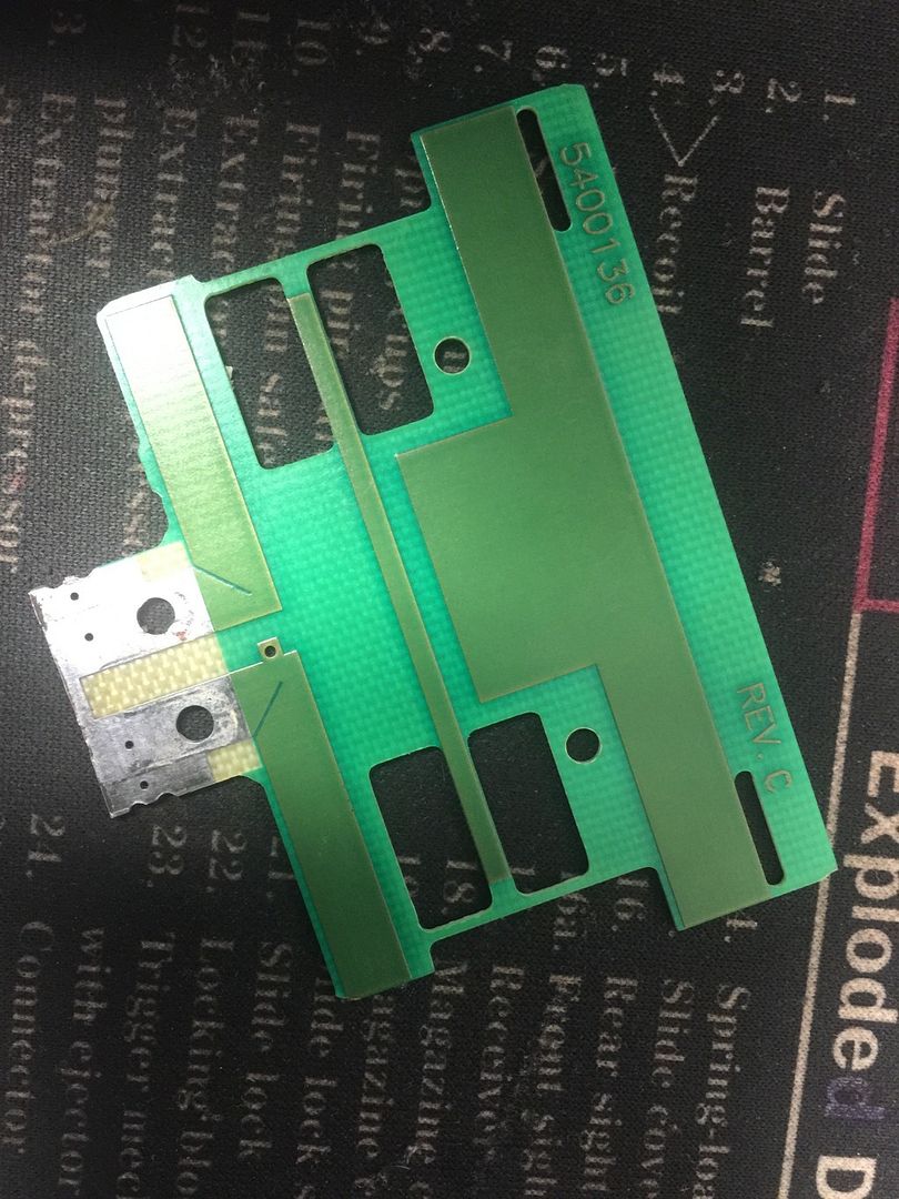
I've removed the up converter and as my 2.4 GHz experience is just starting i have questions.
I'm told that you can attach coax directly to this board, in some configuration, to make it strictly a 2.4 GHz antenna.
I'm unable to find this in a google/bing search or other wise.
Does anyone have knowledge they can share on this?
EDITED: K5DLQ: fixed image links
What was the input/output frequency through the upconverter? Was this something like a 1.2Ghz input and 2.4Ghz output? I don't see any reason why this won't work as long as the antenna is resonant on 2.4Ghz. While the RF propagation has different behaviors at this frequency, same principles still apply. In context that rain gutters have been used for antennas, this would definitely put out a signal :) . Just a matter of how well it works. Maybe the upconverter had a band pass or other filters on it and thus may be more prone to interference, etc.
We've (I have) periodically put Bullets on low power without an antenna (because I didn't have one available at the time) in the lab and have not yet heard of trashing the PA on these low power devices. Consequently, it should be minimal risk to your hardware to dial a Bullet down to ~10dBm, attach to this antenna with the coax direct to the di-pole circuit board and test out. The live test will tell all and can be compared to a known antenna under same conditions.
Joe AE6XE
And, if you don't have proper test gear to measure the ERP of the antenna, you can try putting a current meter in-line with the power injector of your node. Most of the time, you can carefully watch the current draw as it relates to power output of the node. I've done this on 70cm radios to see how well an antenna was matched (since my MFJ-259B doesn't cover 70cm)
The dishes were for a local cable TV company that was in town 20+ years ago and now these antennas can be found all over the place.
I never had service with this company and that was before my time as an amateur operator so i never really looked into the why's and what for's of their equipment.
KD5VSH, Could measure the length of the driven antenna element on the circuit board and see how it relates to 2.4Ghz wavelength. If it's 1/2 wave, etc. then good possibility it will work. Next issue, the picture of the circuit board does not show that there is an embedded balun. Just connecting the (unbalanced) coax straight to a (balanced) dipole would not work very well. Here's an example pic of what an embedded balun looks like:
If resolving these hurdles, then some possibilities to get it working. Put into context you can buy a new 2.4Ghz 27dBi Grid antenna for <$50.
Joe AE6XE
KD5VSH,
You can always take an Exacto knife to the foil antenna if it's too low in frequency, or carefully add bits of wire to the ends to extend it if it's still too high. The trick is patience and craftsmanship if going down this route...suitable antennas start at $50 as Joe noted. In any case, I think it is fun to try it.
:-)
73,
Gordon, W2TTT
201.314.6964
KD5VSH do you have any extra pcb's ? I had a NFG pcb on a grid antenna, and im looking for a replacment pcb like that. I can send a few buck your way for postage.